The Big Red Button - Part 2
Table of Contents
A long time ago I got some hardware from a friend. Among many cool things he gave me 2 over sized red emergency shutoff buttons. I knew that there was a project there. I knew how I was going to do it. But I had no idea what to build.
So let’s recap. I wanted to build the entire project inside the button, which is about the size of 2 stacked decks of cards. I knew I wanted it to do something on my computer and I knew I wanted it to be dramatic, like War Games. I started to brainstorm and then a lot of things interfered.
Last spring I built a stir plate for Cassie. And then we got a really nice soldering station. I did a few smaller projects and finally felt ready to finish this one. Despite this being a hardware project, the software was the hardest part. Because the Digispark is not as widely known as the Arduino, there isn’t as much documentation available. I found myself reading through the source code for the chip’s firmware to figure out how to communicate with the computer over USB. But eventually I got it working.
1. Design
The Digispark uses the ATTiny which has 6 configurable i/o pins. Two are used
for USB communication. I needed one to detect the button press. That left me
with 3 pins to do something cool. I decided to use 2 LEDs, independently
controlled. I was happy with that design - but the sixth, perfectly good, unused
pin bugged me. I decided it would be really cool to have a buzzer go off during
the “arming” sequence and that could use the last pin. With that design I was
fully utilizing the ATTiny.
When you twist the button it pops up and closes the circuit. When you push it, it opens the circuit. I decided the button would begin depressed. You would pull it up to “arm” it, and then push it down to “launch”. These sequences would be accompanied by blinking LEDs and annoying buzzers. Upon “launch” the computer would perform whatever action you had preconfigured.
2. Issues
Embedded programming is not something I am used to. The USB connection
requires constant refreshing and any call that blocks for too long will
kill it. The ATTiny requires you to define a function called loop
which is called constantly as long as the chip is powered. There is no
guarantee how often the loop will be run or at what interval. Nothing
inside the loop function can block. In most of the Arduino tutorials
to blink an LED you do something like this:
digitalWrite(pin, HIGH);
delay(1000);
digitalWrite(pin, LOW);
delay(1000);
However, this will not work because the delay function hangs for too
long and kills the USB connection. To get around this I created some
global variables to keep track of when the LED was lasted cycled. That
looked like this:
int ledState = HIGH;
long previousBlinkMillis = 0;

void blink(int led) {
  long timePassed = millis() - previousBlinkMillis;

  if (timePassed > blinkInterval) {
      // if enough time has passed, toggle the light state
      ledState = !ledState;
      previousBlinkMillis = millis();
  }

  digitalWrite(led, ledState);
}
Debouncing works the same way. If the button has changed states and remained in the new state for a certain amount of time, you can safely assume it was actually pushed. Because the button is a mechanical device the connection when it is first pressed or released may ’bounce’ open and closed. You need to account for this in the program, otherwise there may be intermittent bugs.
long lastDebounceTime = 0; // last time the input was toggled
long debounceDelay = 50;

void handleButton() {
  int reading = digitalRead(button); long time = millis();

  if ((time - lastDebounceTime) > debounceDelay) {
      // whatever the reading is, it's been there for more than
      // the debounce delay, so take it as the current state:
      // ...
  }
}
The next issue was hardware-related. The buzzer requires 5 volts. The
pins are supposed to output 5V, but this is the real world and specs
come with a +\- tolerance. The pin was only putting out 4.5V, which
was not enough to run the buzzer. Fortunately the positive rail was
actually supplying 5V, so I just needed a way to turn the rail on or off
for just the buzzer. This is the perfect use-case for a transistor. Sure
enough, running the 5V rail into the base of an NPN transistor and pin 6
into the collector did the trick. I was able to use the transistor as a
valve, and turn the 5V rail on or off for the buzzer using a smaller
voltage.
3. Execution
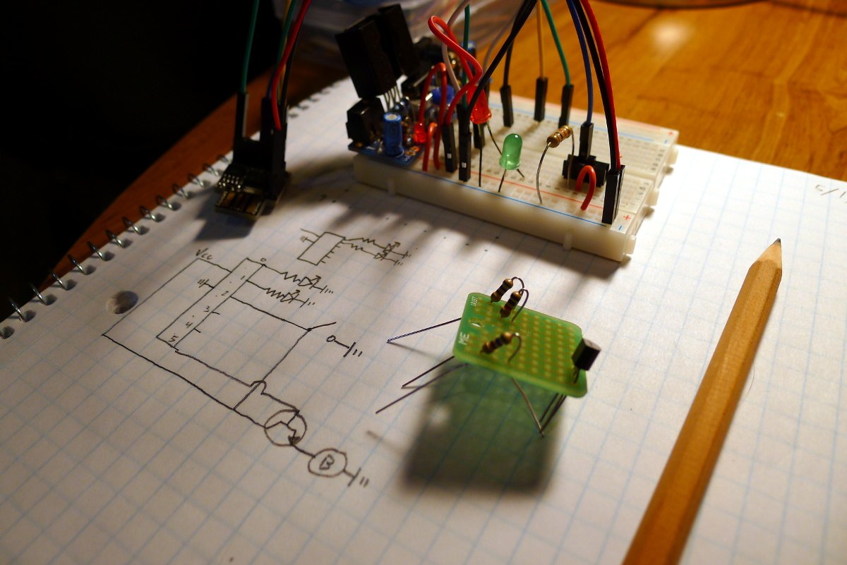
I decided to use a small perfboard to hold all of the non-Digispark components. This one from Sparkfun, has traces which connect every 3 pins, so you can solder two components together on the board, without free-soldering the components directly.
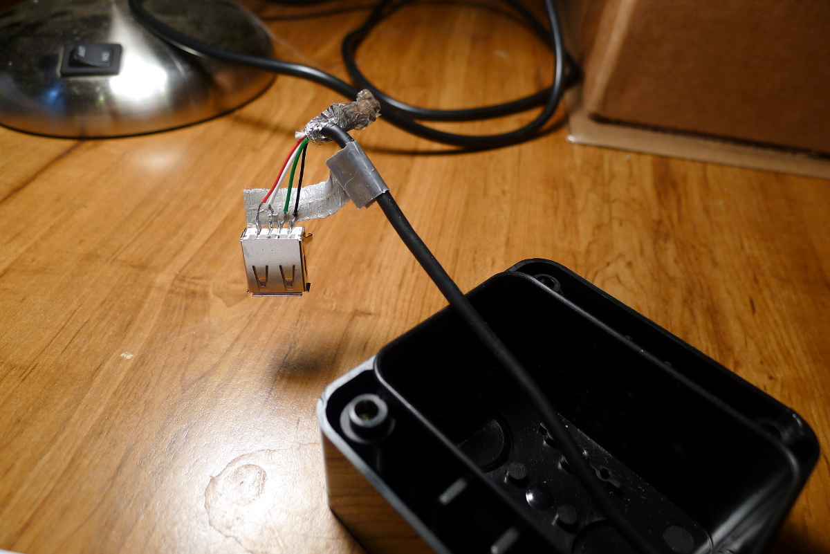
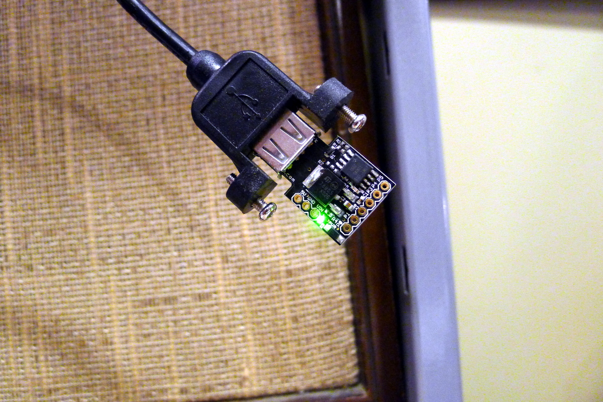
To connect the Digispark to the computer with USB, I drilled a small hole in the case, cut the end of a regular USB cable, ran it through the hole and attached a new USB connection inside the case.
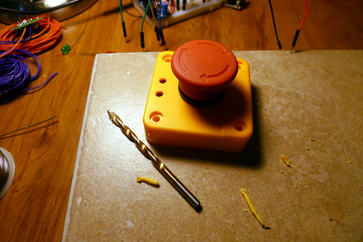
I drilled out the two holes for the LEDs on the top of the enclosure.
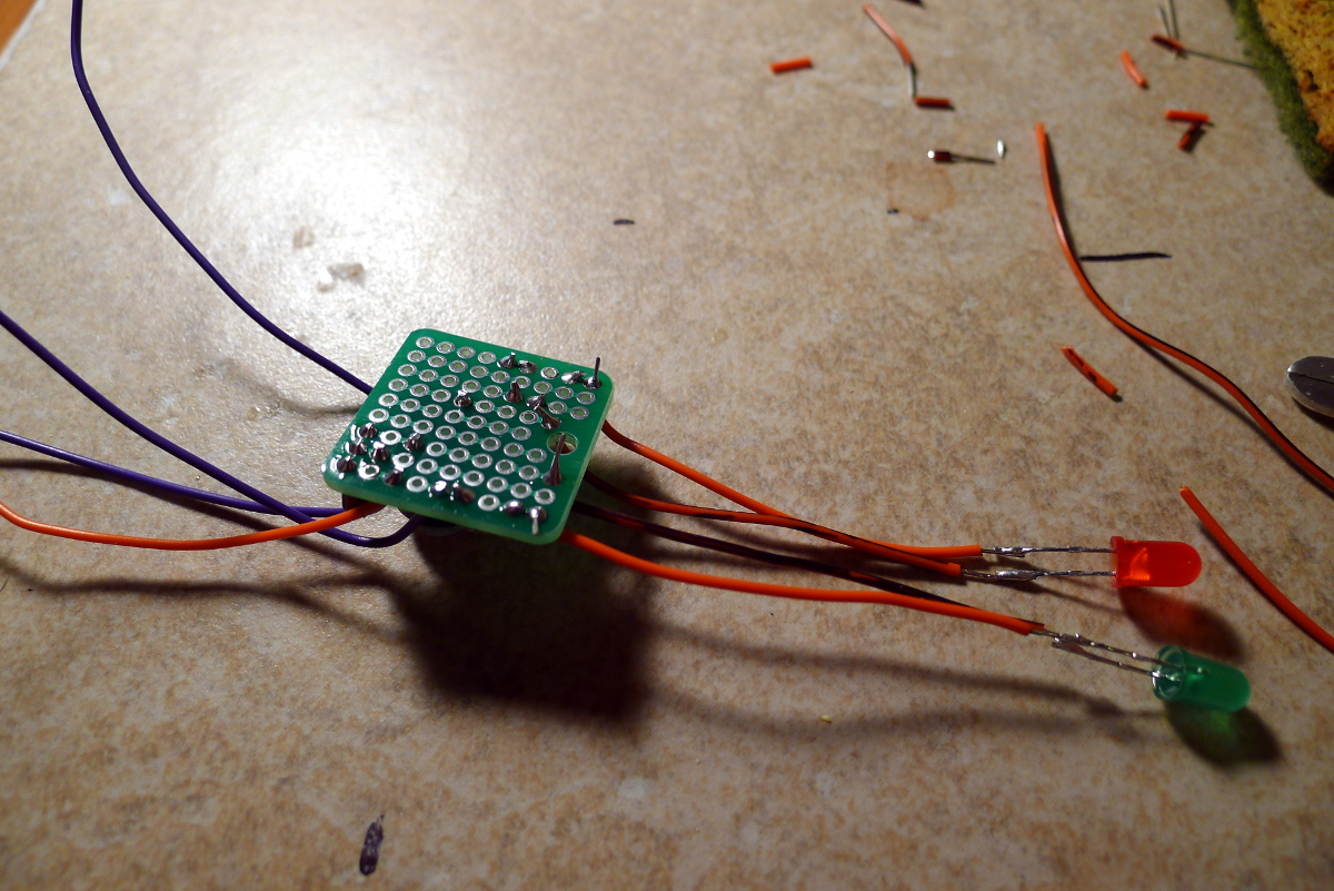
Attaching the LEDs.
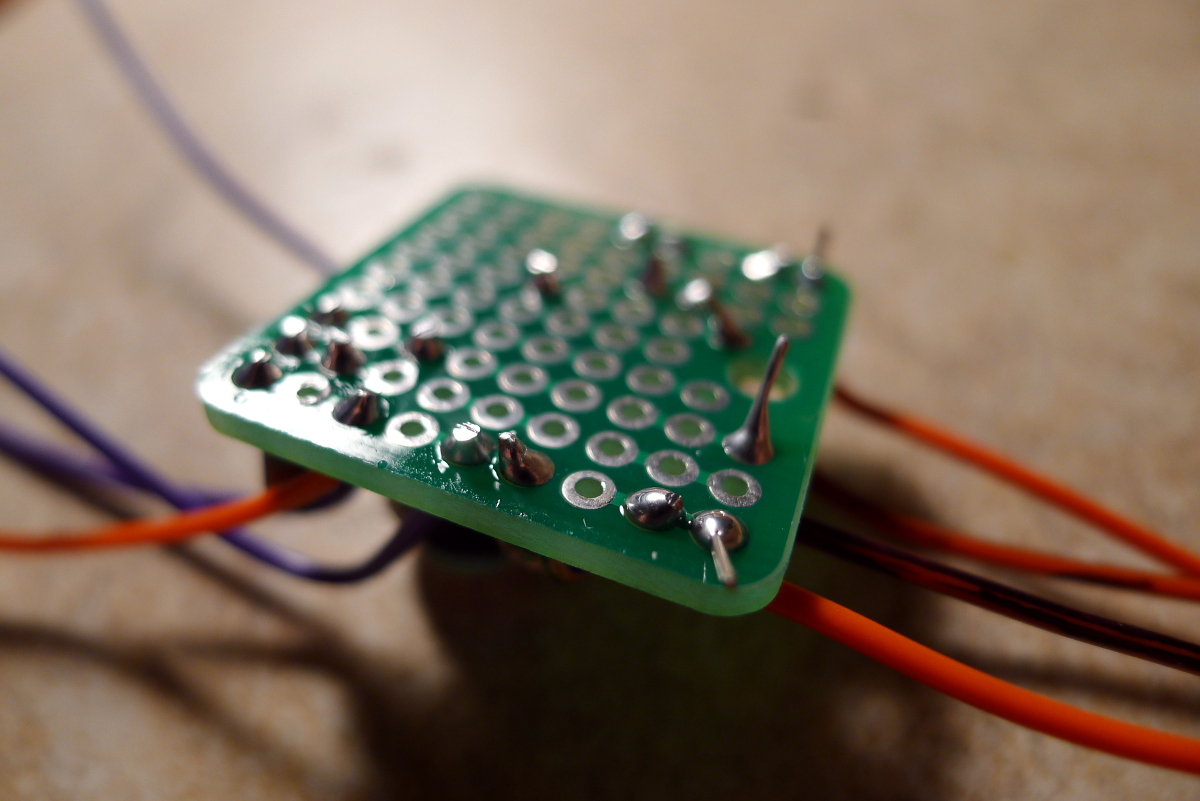
My soldering was not the best on this one.
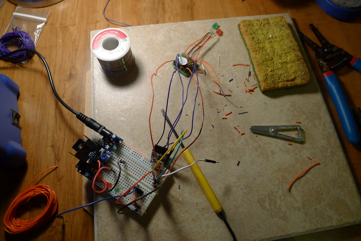
Testing everything one more time.
Testing everything again.
Loading the program onto the Digispark.
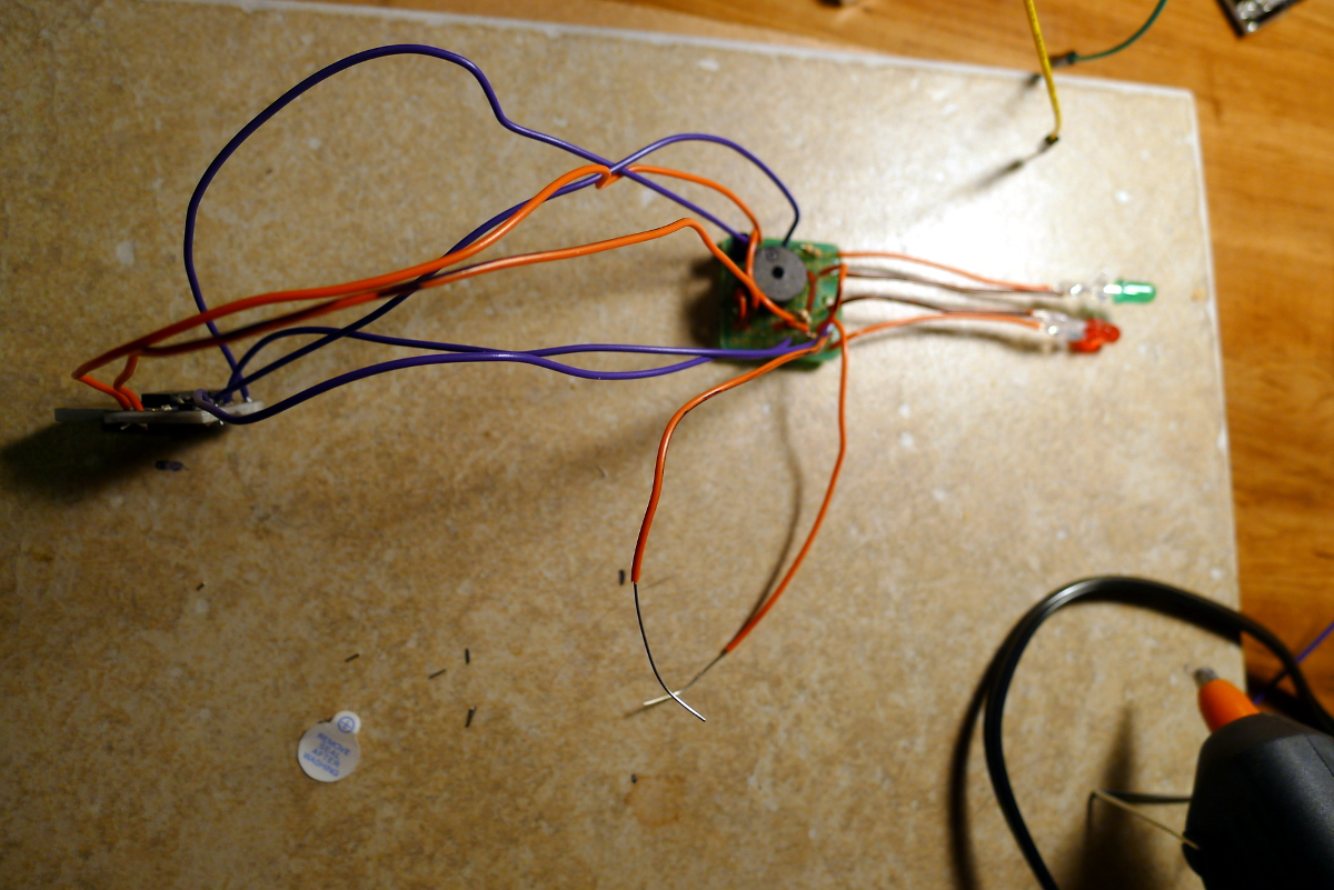
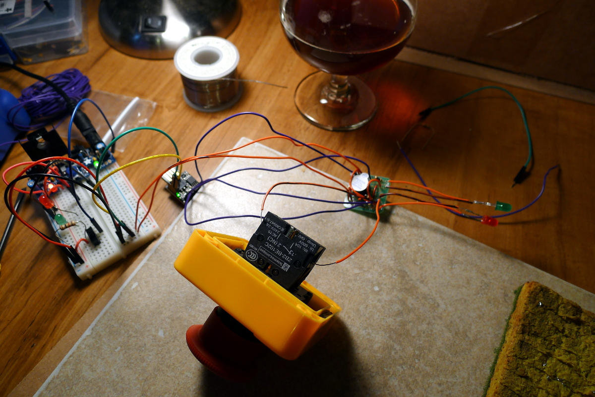
The completed circuit. (I needed to neatly jam all of those wires into the small case.)
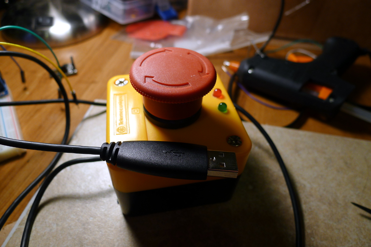
The finished product.
3.1. The way it works
- Twist the button to arm it. This will sound a buzzer and flash the LEDs.
- When the button is pressed while armed, a command is sent to the connected computer.
- The computer runs the command and returns the status. The button displays an LED status accordingly.
- If the button is armed and not pressed for 30 seconds, it resets.
4. The Daemon
The hardware portion of this project is just an input device for the computer, so I needed some software on the computer to handle the USB connection and run whatever command was preconfigured. I used Ruby to prototype the USB connection and then just stuck with it for the daemon. There’s a good Digispark library out there. The logic of the daemon is pretty simple.
spark = DigiUSB.Sparks.last

loop do # try to get a char char = spark.getc
  if char != ""
    handle(char)
  else
    sleep 1
  end
end
The code to handle the incoming USB message is here:
def handle(char)
  if char == "l"
    # fork process and run external command
    pid = fork { exec external_command }

    # check status of fork
    _, status = Process.waitpid2(pid)

    # return a y/n to the button
    if status.success?
      spark.putc("y")
    else
      spark.putc("n")
    end
  end
end
It’s not yet daemonized, but it gets the job done. I just got a shipment of really cool parts, so I expect to start the next project soon. Hopefully it won’t take as long to finish.
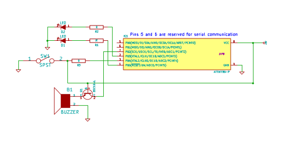
5. Schematic
Here’s the final design. I haven’t included the power supply or USB hookup because those things are part of the Digispark itself. Pins 5 and 6 are tied directly to the data pins of the USB connector. Other than that, there is a voltage regulator to clean up the 5 volts coming over USB.