Building a guitar pedal
I woke up New Year’s Day groggy with a slight hangover. What better cure than strong coffee and solder fumes? So down to the basement! There was a project already on the bench that just needed a few more wires.
I have a large tube amp that has been gathering dust since I moved to the city. Now that I don’t share walls with anyone it’s time to revive it. I’ve never been completely happy with the sound. Fortunately, the world of guitar electronics is much less complicated than other electronics and you can still tinker without needing an advanced degree.
My plan for the amp is to switch the power tubes (to brighten the sound), leave out half of them (to lower the volume), get a smaller speaker cabinet (to lower the volume further), run an EQ in the effects loop (to shape the sound a little more) and drive the amp with a boost pedal (to increase the guitar signal and overdrive the tubes.)
Working in reverse order the first item on the list was the boost pedal. Not content to buy one and move on I decided to build one. There are many different kinds of boost pedals. Some increase the signal without coloring it - clean boost. Others increase the signal to the point of clipping - overdrive. Most have some tone controls to cut or boost frequencies. There is a legendary overdrive pedal called the Tube Screamer that I have always wanted to try. People much smarter than myself like to reverse engineer guitar pedals and post the schematics online. I found such a version and decided to build it.
The website hosting the plans sells printed circuit boards. I bought one of their boards and ordered the rest of the parts. The circuit board is just for the effect - it doesn’t include anything for turning the effect on or off or even connecting it to a guitar signal. That part is left up to you. I looked up how to do this and ordered the extra supplies to build a complete pedal.
When everything arrived I soldered the components onto the circuit board. I wanted to test it before wiring up the enclosure so I built a test bracket and wired the board onto that. I was getting power from a small power supply that I use for prototyping. I connected my guitar and the amp to the test bracket and held my breath as I turned everything on. No smoke! But also no sound.
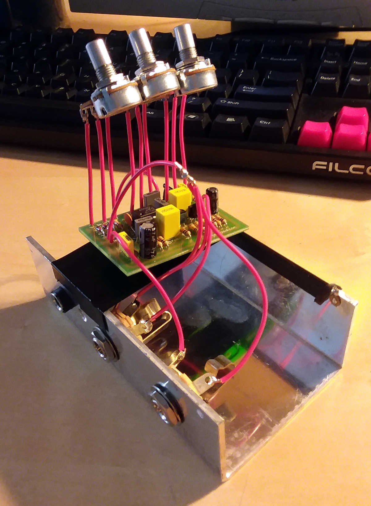
The board set up for testing
I double-checked every connection, making sure I had placed all of the components correctly. Then I saw the problem. I was supplying 5V of power when the circuit needed 9V. Classic. When I switched to 9V I heard the speaker in the amp buzz to life. I plucked a few strings on the guitar and the amp responded. The sound was nice - a crisp crunch. It was working!
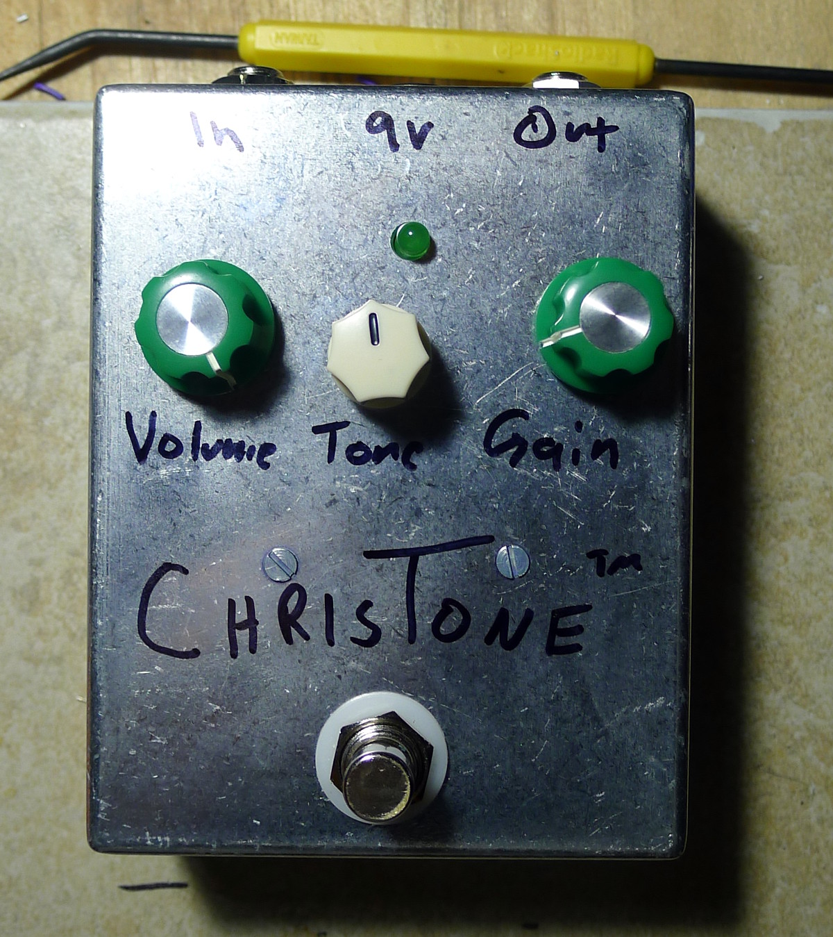
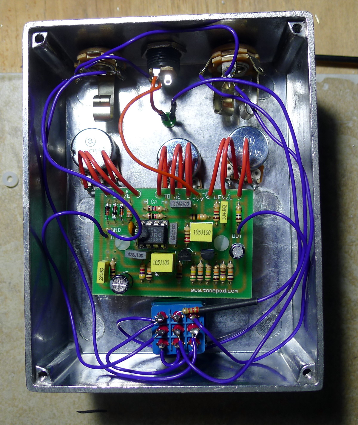
To house the effect I used a metal box about the size of 2 decks of playing cards. With calipers I carefully measured out where I wanted the holes for knobs and jacks. I drilled them all out. Unfortunately I did not measure perfectly so the finished product looks hand-made. (I prefer the term “artisanal.”) After placing the knobs and jacks in the enclosure it was time to wire it all together. This was the most difficult part of the project because it involved a lot of wire routing and free-hand soldering. It’s nice to have plenty of wire to work with, but in a small enclosure it can easily become a headache.
The wiring scheme I used is called “true bypass” because when the pedal is turned off the guitar signal is completely bypassing the effect. Most mass-produced pedals are not true bypass. The guitar signal is always undergoing some processing. Each style has dis/advantages. Non-true-bypass involves extra circuitry, and for homebrew pedals doesn’t make sense. My pedal uses a double-throw switch to send the guitar signal either through the effect circuit and then to the output (when on) or straight to the output (when off.)
When the solder had cooled I took the pedal upstairs and again connected it between the guitar and the amp. I turned everything on. No smoke! But again no sound. The pedal has a green LED to show when it’s turned on. This did not light up, so presumably the issue was power. I was using a 9V adapter with a barrel plug to power the pedal. I switched it with an adapter from one of my guitar pedals and that worked. But why? I knew the first adapter was working because I tested it in another piece of equipment. The answer still puzzles me, but I guess it’s “just how it is.” A barrel plug has 2 connections - the outside of the barrel is called the sleeve and the inside (which is electrically isolated) is called the tip. Every power supply I have ever used puts the ground on the sleeve and the voltage on the tip. Except guitar pedals. For whatever reason they use the tip as the ground and supply voltage on the sleeve. I should have fried my pedal when I plugged in the first adapter and ran the current backwards. Fortunately the LED saved the day. (An LED is a diode and current can only flow in one direction through it.)
Here’s the finished product.