Lets Build A Tube Amplifier
Table of Contents
1. The setup
A few years ago I wrote about building a guitar distortion pedal. The pedal was intended to be the first part of my grand plan to finally get my large, heavy-metal amplifier to sound better. Make no mistake, the amplifier sounds great for a certain style of music and plenty of knowledgeable people on internet forums swear on their lives that if your large, heavy-metal amplifier doesn’t sound good you just need to spend more time tweaking its settings. Fair enough I suppose.
But one day I had an honest conversation with myself and realized that for all of the money I was prepared to pour into my old amp, I could just buy a different amp that sounded the way I wanted without any additional gear or tweaks. Good point, self.
Where to begin though? As far as amps go, there are big name classics and tons of small boutique manufacturers. The variety is overwhelming. I looked up what my favorite bands had used on my favorite albums and even that didn’t limit the choices much. I watched hours of demo videos on YouTube to get an idea of how various amps sounded. I realized that just like the “best” camera is the one you’re currently holding, the “best” amp is the one you’ll play. I decided to go with the first one that seemed interesting.
My requirements were simple - I wanted the amp to be small and I wanted it to use vacuum tubes. Tubes are an obsolete technology still used in guitar amplifiers because when you push them hard (by turning up the volume and running more current through them) they distort the sound in a very pleasing way. This is called breakup and it only happens at higher volumes - hence the desire for a small amp that I could push without losing my hearing and pissing off my neighbors.
Eventually I came across a demo video of some old Fender amplifiers. Fender began by making electric guitars but quickly followed up with amplifiers. I hadn’t considered a Fender amp because they have a reputation for being very clean no matter how loud you turn them up. That was the opposite of what I wanted. However one of the amps in this particular video was a Fender amp I had never seen before. It was older, dressed in brown rather than black like every Fender I had ever seen, and it sounded great - very crunchy and distorted. I was intrigued. I discovered that the first models of Fender amps were not clean at all. In fact they started to break up at very low volumes. The company worked to correct this and eventually did, but not before selling quite a few of the earlier, dirtier amps.
I located several of these brown Fenders on gear resale websites but they were very expensive. This model was produced for a few years in the early 1960s. They are collectors items if they even work. I didn’t see any point in spending thousands of dollars to buy an antique that might need a lot of maintenance to operate properly.
But then I got another idea.
2. The crazy idea
I was able to build a distortion pedal because that kind of audio signal processing is not complicated. My pedal is completely analog and uses very simple components. Tube amplifiers are also completely analog and use simple components. Unlike pedals, amplifiers tend to come with schematics. And even if they didn’t, these circuits were designed in the early 60s. They don’t use microchips. There’s no way to hide what’s happening in the circuit. They were built to be repairable. They have no secrets. I could just build one.
I wasn’t keen to start from scratch with amplifier theory. I just wanted a working amp that sounded like the vintage brown Fenders. After a little bit of searching I discovered a company that sells amplifier kits. They had all kinds. Most were clones of famous vintage amps and to my delight they actually sold a clone of the brown Fender I had my eyes on. It was actually affordable. It was all too good to be true. I dusted off my large, heavy-metal amp, carted it to a music store and sold it. Then I ordered the amp kit.
3. The execution
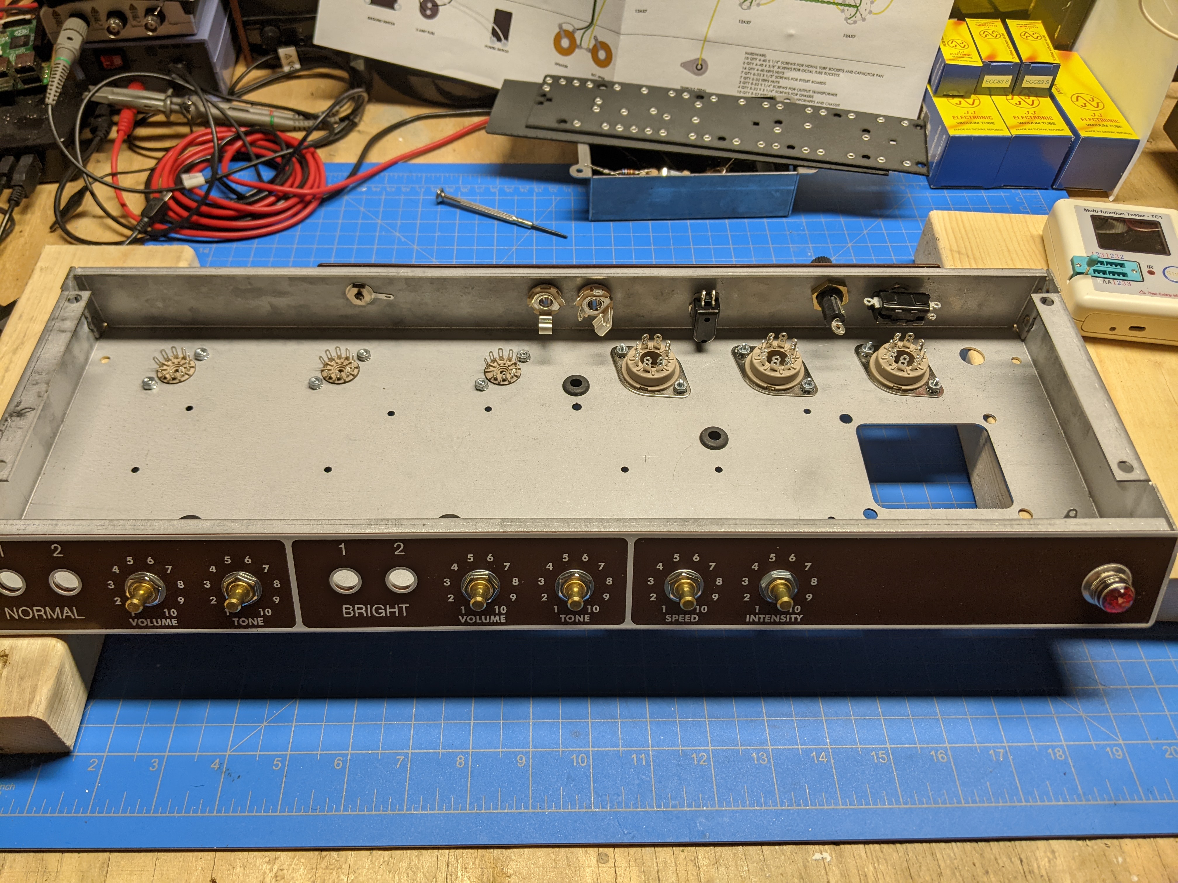
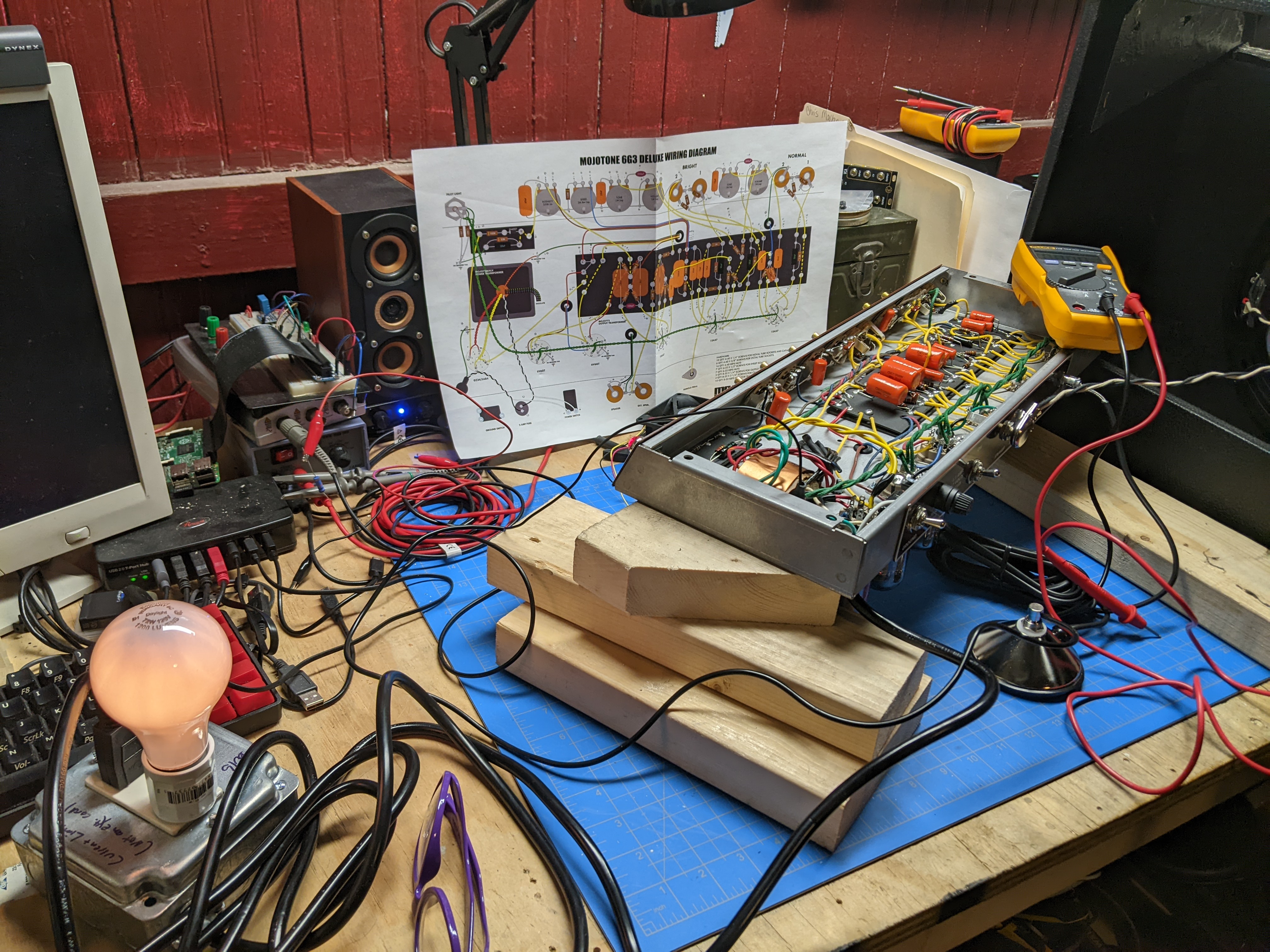
When everything arrived a few weeks later I unpacked it and felt really excited and really overwhelmed. Building a pedal is one thing, but an amp is an order of magnitude more complicated. After getting organized I set to work installing all of the fixtures in the chassis. The foundation of the kit is a steel chassis with holes punched for external components. The main board sits inside and other larger components hang off of the underside. I installed some external hardware first. The amp has 6 tubes, 2 transformers and a variety of knobs, jacks and switches. The ruby red pilot light was very cool but a total pain to install. Apparently this light is actually an aircraft part.

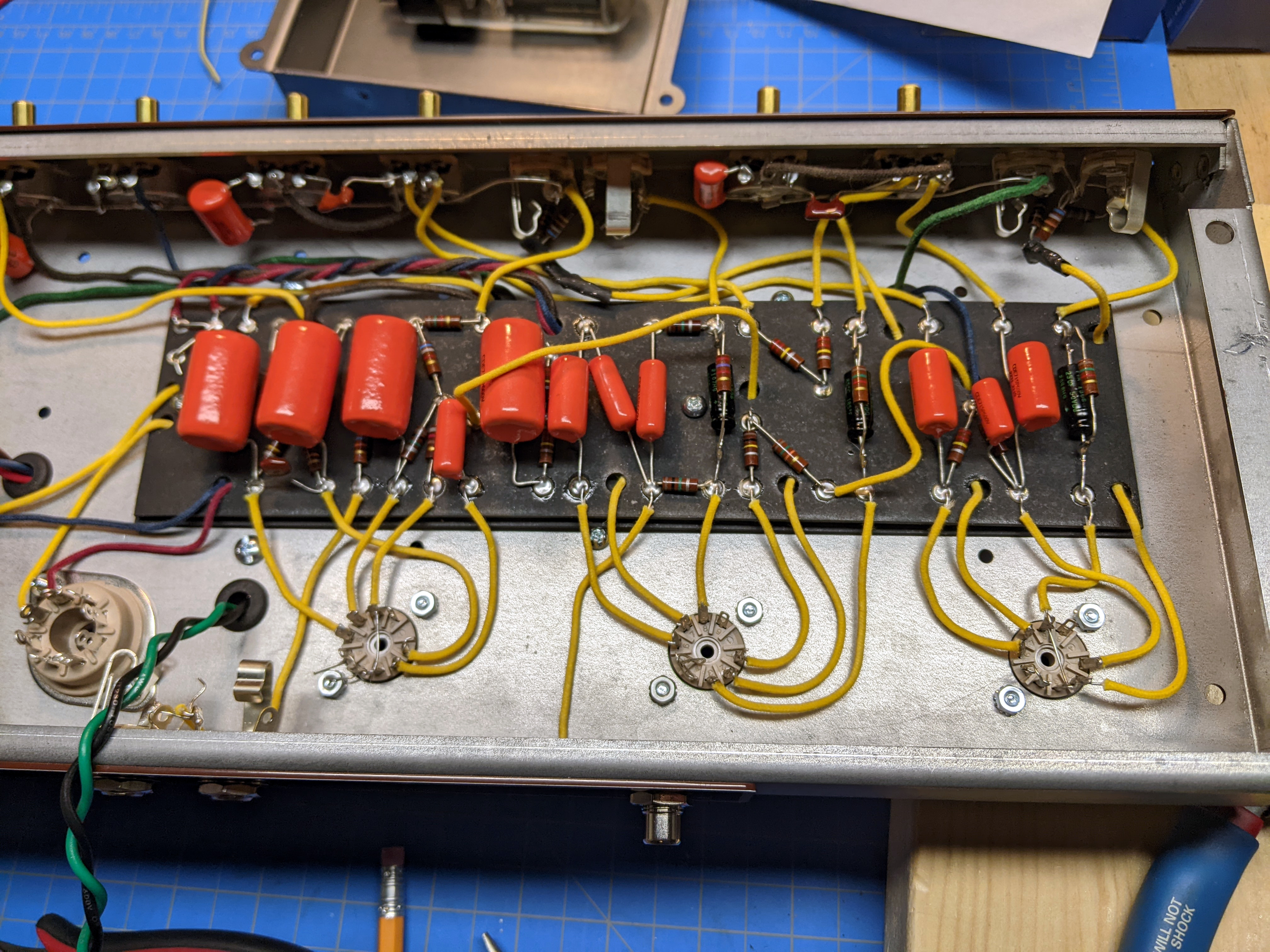
With the chassis mostly done I switched to the circuit boards - this amp has three. Unlike modern printed circuit boards with copper traces connecting everything, these boards were rectangles of non-conductive fiberboard with eyelets riveted through where connections occurred. To use them you run two or more wires/components into the eyelet and fill it with solder. I started with the two smaller boards - one for the tube bias and one for the large filter capacitors that sit under the chassis. Then I worked on the main board. This is the most complicated part of the amp and I moved slowly. This work consisted of looking at the circuit diagram, finding the part in the box of components, testing it to make sure its value was in line with the schematic and then bending the leads and setting it into place. I didn’t solder anything on this board yet.

When the boards were populated I double and triple checked my work. I really wanted everything to work the first time. Most of the components on these boards connect to other things - jacks, potentiometers, and tube sockets. I cut lengths of wire for all of these connections, making sure to leave plenty of extra. I would cut them down to final length later. With these connecting wires all cut and placed I could begin soldering. (Having watched videos of other people doing this, it seemed like a good idea to do as much soldering outside the chassis as possible.)

Next I turned to the front panel which consists of various jacks and pots. The front of the chassis is angled and it’s tricky to get to some of the connections. One trick I learned from others who had built amps was to assemble the front panel electronics on the outside of the chassis using the holes to keep everything spaced correctly. This worked perfectly.
To ground the pots you can use the chassis itself, but stray voltage can cause hum in a circuit like this so I used a ground wire and tied all the pots together. I had to scratch the back of each pot in a crosshatch pattern to help the solder adhere. When the front panel was done I carefully removed it from the front of the chassis and flipped it around.

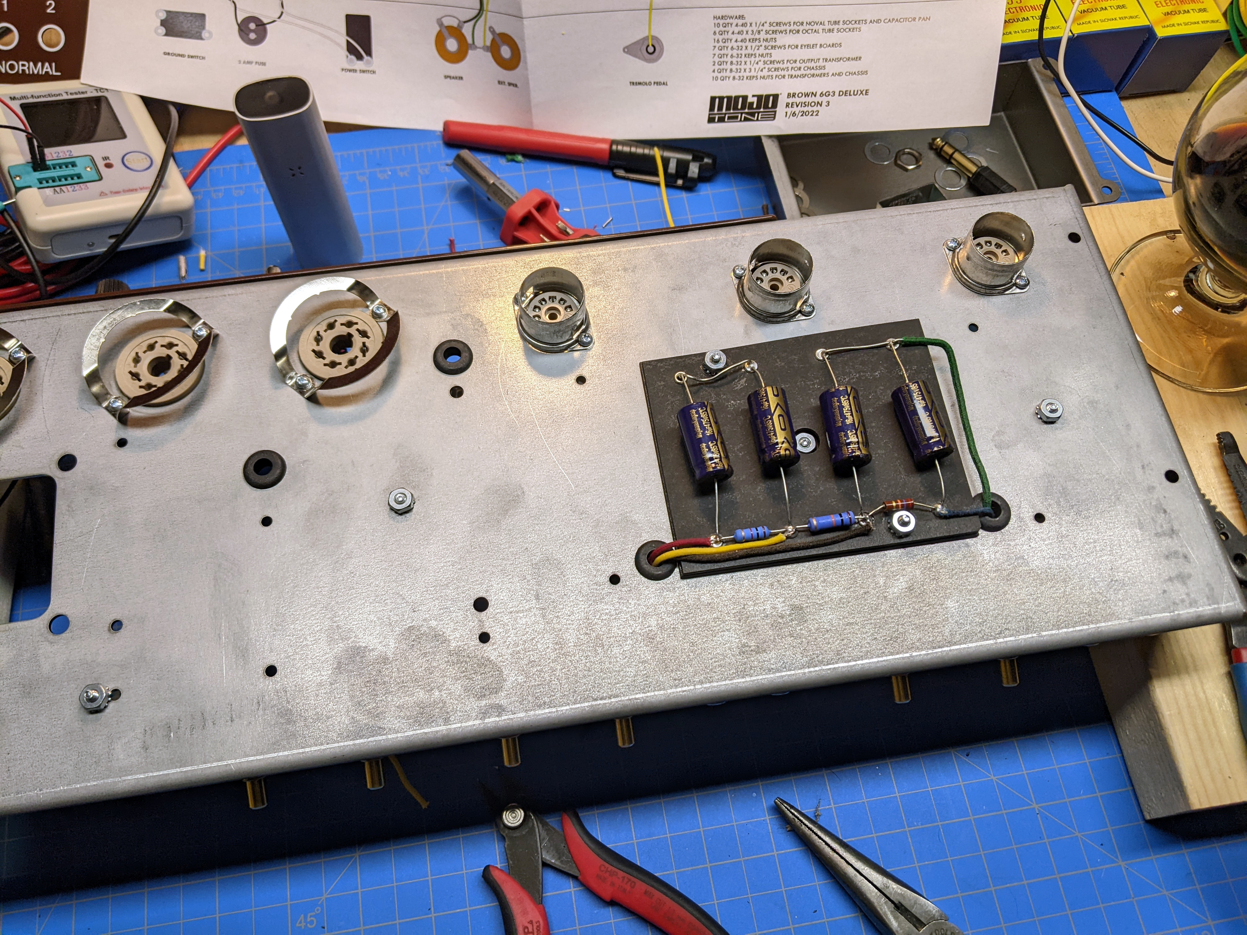
I screwed down the bias and capacitor boards. The bias board is over by the power transformer and the capacitor board attaches to the underside of the chassis. There is a metal cover that goes over it called the dog house. It doesn’t look like a dog house to me, but I like the name. Bias voltage is used to keep the tubes within their design limits. On a basic level, a tube for amplification has 3 parts - a cathode which is heated to release electrons, a positively charged plate to collect the electrons, and a wire mesh in between the two called the grid. By applying a positive or negative voltage to the grid you can vary the flow of electrons from the cathode to the plate. It’s like squeezing a garden hose in the middle to slow the flow of water. Bias is a permanent negative voltage on the grid, to keep the flow of electrons from cathode to plate under control. If the bias is too low the tube is said to be “hot” both figuratively and literally as too much current flow will cause the tube to heat up, sometimes beyond its design limits leading to a shorter life. If the bias is too high the tube is “cold” and the signal (as variations in voltage on the grid) is not amplified as much. This amp has fixed bias meaning the bias doesn’t change (some circuits have other biasing schemes) and the bias is set by a resistor of a predetermined value. Some amps include a potentiometer in the bias circuit so that the bias can be fine tuned - more on this later.
Now it was time to mount the main board and begin connecting it. The fiberboard is held down by a few screws. There is another layer of fiberboard underneath it to prevent anything grounding out on the chassis. Working from right to left I took the wires I had soldered into the board, cut them to their final lengths and soldered them to the external components. This wiring is where the skill of the amp builder really shows. Every wire is a potential antenna so you want to keep them short and flat to the chassis. I avoided crossing wires as much as possible. Any time wires have to run next to one another I gave them a twist to minimize interference and noise.
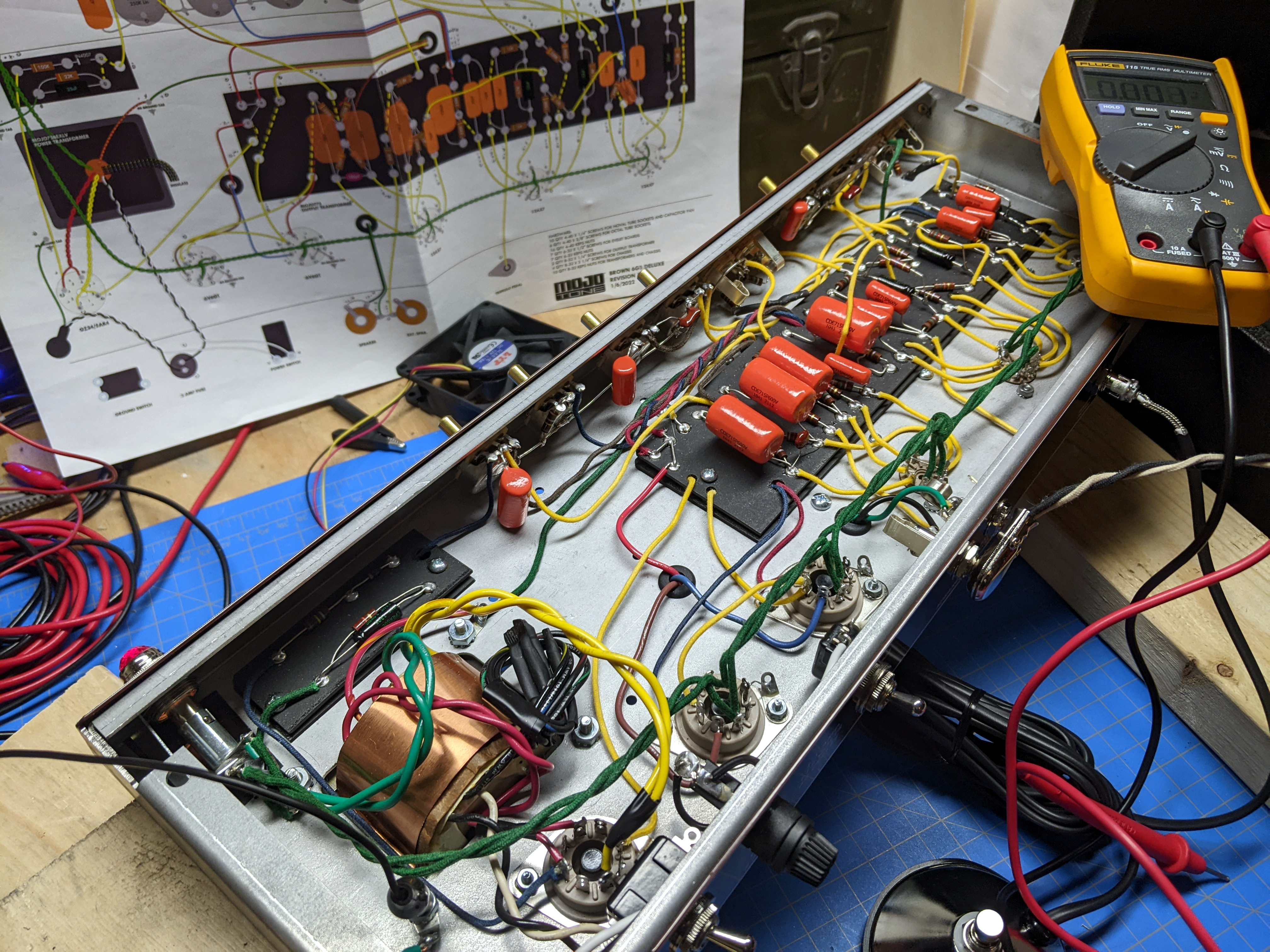
Finally I attached the transformers to the bottom of the chassis. The larger of the two is the power transformer. It converts the 120 volts from the wall into other useful AC voltages. (It isn’t necessary to understand how transformers work, just that they “transform” one voltage into one or more different voltages.) The power transformer was so heavy that it could hold the rest of the chassis upright even though it sat far to one side. It had a few pairs of wires coming out of it - each with a different AC voltage. I connected two pairs to the rectifier tube - one for the heater, and one for the AC voltage being rectified. Rectification is the process of turning an AC voltage which looks like a sine wave into a DC voltage which looks like a horizontal line. Another pair of wires from the transformer went to the pilot light and then to every tube socket in a daisy chain configuration to power the tube heaters. The output transformer is smaller and converts the high voltage, low current output from the power tubes into a low voltage, high current input for the speaker.

After wiring a power cord through the on/off switch and fuse to the power transformer the amp circuit was complete. Before testing I built a device to limit the current going to the amp in the event I had miswired or shorted something. This was a standard electrical outlet wired in a way to run the current through a light bulb. The reason being that if there was a large current draw (from a short, for instance) it would hit the light bulb first - which would not only bleed off most of it into light and heat, but also alert me that something was wrong. I plugged it all into a GFCI outlet for extra protection.
4. Flipping the switch
I began the test by giving the amp power without any tubes installed. The power transformer would be the only thing energized. When I flipped the switch the pilot light illuminated (recall that it is connected directly to one of the transformer outputs). This was a great sign! No smoke! The light bulb was barely glowing - indicating that the amp was not drawing excessive current. I carefully checked the voltage at the only places receiving current - the pilot light, the inputs for the rectifier tube and the heater pins at each tube socket. Everything was normal.
The next step was to turn power off, plug in the rectifier and check voltages at test points in the circuit. The kit came with a sheet marking all the test points and which voltages should be observed where. At this point I was dealing with lethal voltages, so I clipped one of the multimeter’s probes to ground and only used one hand to probe the test points. Working this way, if you get shocked it will still be bad, but the current won’t have an easy path through your heart like it would if you were working with both hands. Observing correct voltages at all the test points I powered the amp off and prepared to socket the rest of the tubes. Before doing this I measured the voltage on the large capacitors in the dog house and they were still energized - capacitors will hold a charge for a long time. I made sure to bleed them with a large resistor to ground (and double checked with the multimeter) before continuing.
When the tubes were in I connected the speaker. The speaker is part of the circuit and provides electrical resistance. It’s not good if you run a tube amp without a speaker for any amount of time. I flipped the power switch, gave the tubes a minute to warm up and checked the test points again. Everything was in order. I carefully plugged a guitar cable into the input, turned the volume up a hair and touched the end of the cable with my finger. The speaker buzzed! Grabbing a guitar, I plugged it in and strummed a chord. It was one of the most satisfying chords I’ve ever played.
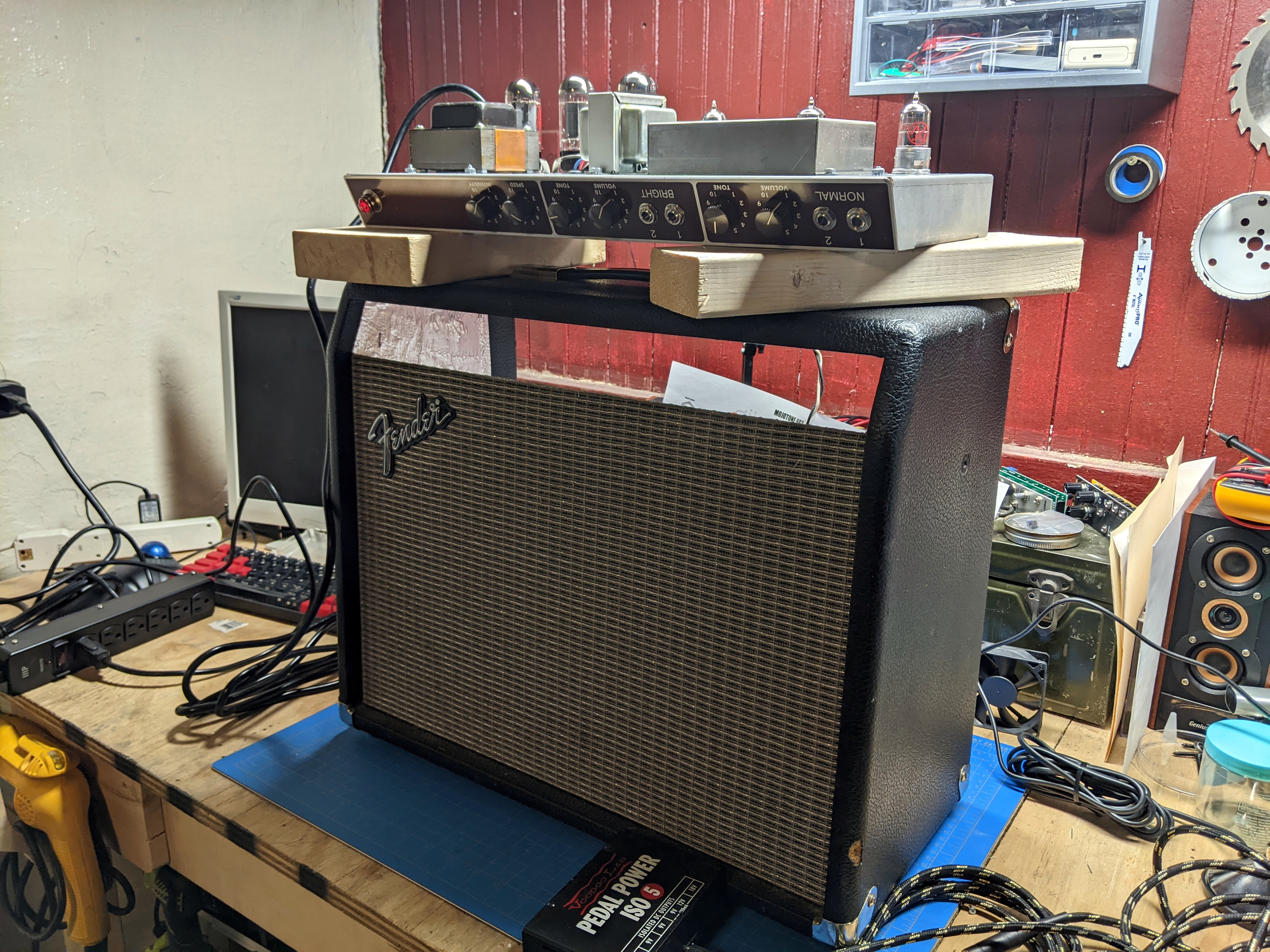
I had assembled the kit without making any mistakes. That was quite a relief. It’s true the kit was much less expensive than a vintage amp, but it still wasn’t cheap. I had an older amp that looked like it might fit the chassis and I was hoping I could use its cabinet until I found time to make my own. Unfortunately the new chassis was too wide. I mounted the speaker in the old cabinet and set the chassis upside down on some 2x4 pieces resting on top. This would allow me to play the amp while I built a cabinet. I used it in this configuration for a few months. I think it looked pretty cool, but I knew it would look cooler with a new cabinet of its own.
5. The enclosure
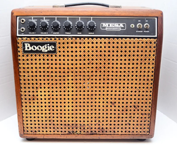
An amplifier is just a wooden box that holds the circuit and speaker(s). Even with my limited woodworking experience I figured I could build a box. I had a certain look in mind. There is an amp by Mesa Boogie that was dressed in a natural wood box with a wicker grill. I loved the look of it and sought to reproduce it.
To build the box I needed lumber. Boxes work best when they’re square so I needed square lumber. Better woodworkers have nice things like jointers, planers and table saws to get their wood flat and square but I didn’t have any of that. Fortunately one of my local hardware stores sells “project lumber” which is already square and plane. It comes shrink wrapped. I felt ridiculous buying shrink-wrapped lumber but humidity can warp wood so I understood the need.
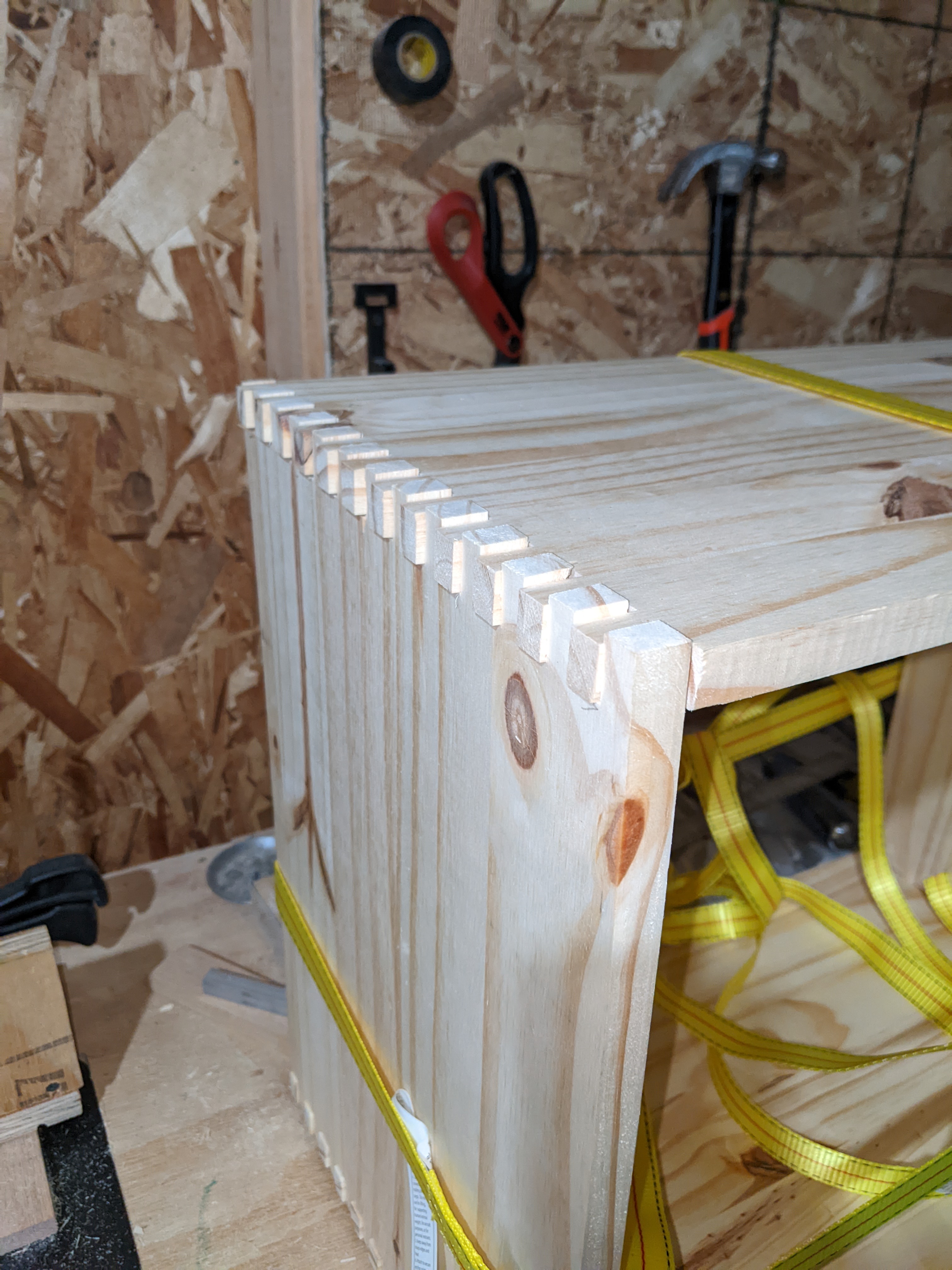
Next was deciding how to join the wood together. You can butt the end of one piece up to another and fasten it with glue and nails but the joint is not pretty and not as strong as it could be. The next level up is called a box joint. The idea is that you cut evenly spaced notches in the ends of the boards - like a person intertwining their fingers. The joint is very strong and looks attractive. Even better is the dovetail joint, but I didn’t attempt that so I won’t go into it. Box joints are relatively easy with the right tools and a little practice. I already had a router so I knew I could do it.
I did not have a router table, so I bought a base plate and routed a hole in the top of my garage workbench. The plate fit into the hole and was level with the bench top. Rather than build a box joint jig, I found an inexpensive jig that looked like it would work with my setup. I decided to make my fingers 1/2 inch because my project wood was 1/2 inch thick. I screwed the router base plate to the work bench and secured the box joint jig on top of it. Then I built a fence that could slide back and forth over the router bit. The idea was to clamp the work piece to the fence and move it over the router bit to cut a groove, then move it over 1 inch and repeat the process. This way I would have a 1/2 inch groove, then a 1/2 inch finger, then a groove, then a finger, etc.
The process is simple, but the execution takes practice. I spent one entire weekend making test cuts. The hard part is keeping in your mind where each piece goes and where the fingers need to be. For example, if your top piece starts with a finger, your side pieces need to start with grooves and your bottom piece needs to start with a finger so that they all line up. To keep all of the cuts consistent you clamp matching pieces (top/bottom and left/right) and cut them together. It can get a little confusing to keep track of everything and I made some mistakes practicing on the test pieces. Eventually I got something that resembled a box and all of the fingers lined up.
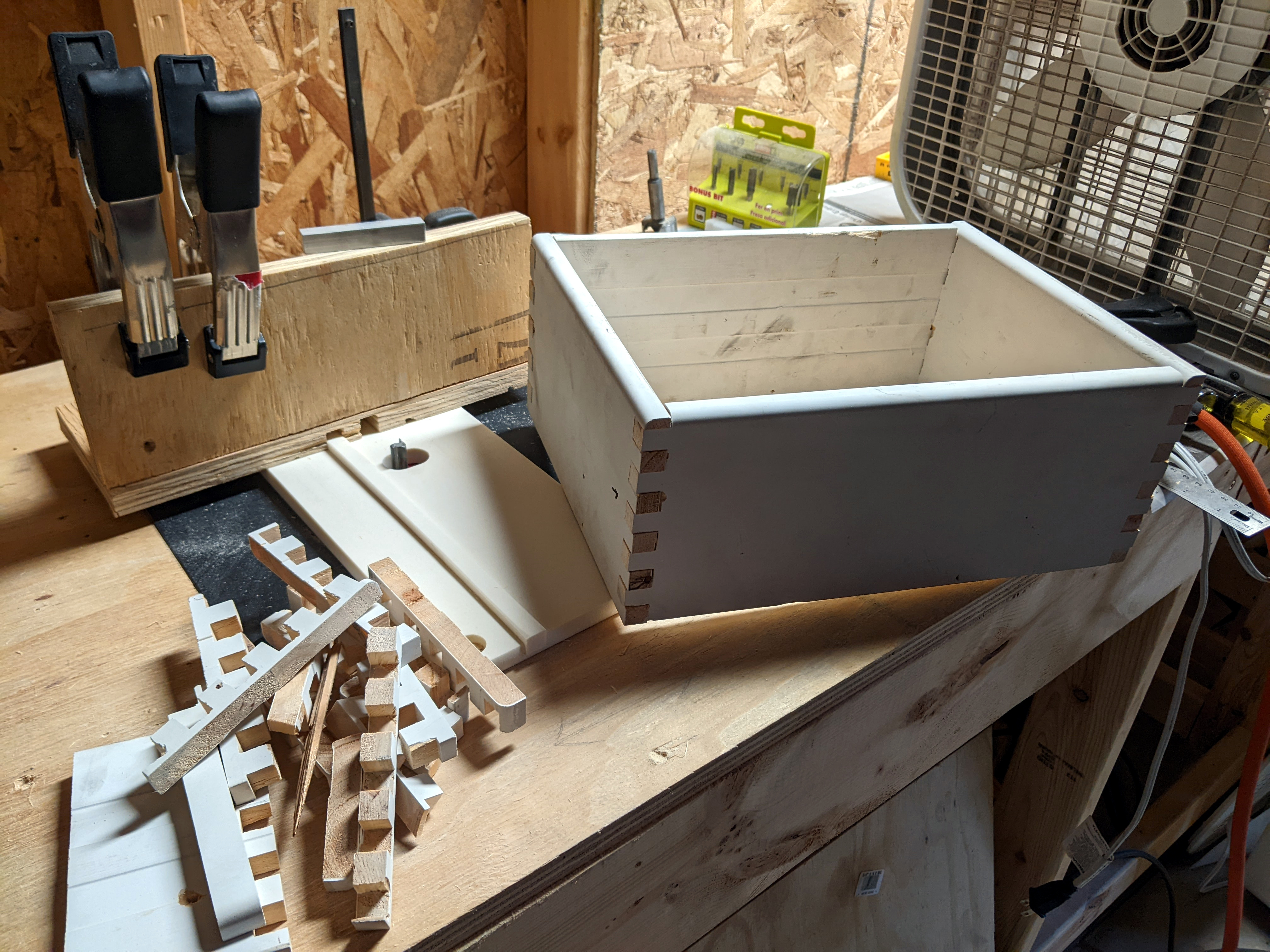
I carefully measured and marked the project wood and cut it to rough dimensions with a circular saw. The wood was wider than I wanted meaning the amp cabinet would be too deep but I planned to deal with that after I had joined the wood into a box. I left the pieces a little long. Obviously it’s easy to remove material and hard to put it back. I spent a very stressful Saturday cutting out all the fingers with my router jig. I placed a small piece of sacrificial wood behind the work pieces to prevent tearout - when the bit breaks through the back of the work piece and tears out material from around the cut. I also made shallow cuts. I set the router depth-stop at the desired depth but then backed it off and made the full cut in several passes increasing the depth for each pass. This way I wasn’t removing too much material with each pass. When I finished all the cuts I held my breath and fitted the pieces together. It looked pretty good! Everything lined up. I was happy I had spent all that extra time practicing.
Next came the glue up. I needed a way to hold everything tight while the glue dried. Clamps are the obvious solution but I didn’t have any long enough and clamps can be surprisingly expensive. I decided to try some cheap ratchet straps with 2x4s and strips of wood to space them out. This worked well. My box had a lot of surfaces to glue and I knew the working time for most wood glue was not long. I practiced applying the glue by going through the motions with a small dry brush and found I could not glue the entire project fast enough before the glue was supposed to get tacky. I decided to do one joint at a time. This only works for the first two joints. After that you have to glue two joints at once. But I practiced on the first two single joints and got the double done with enough working time. The ratchet straps and spacers worked well and saved me from buying more clamps.

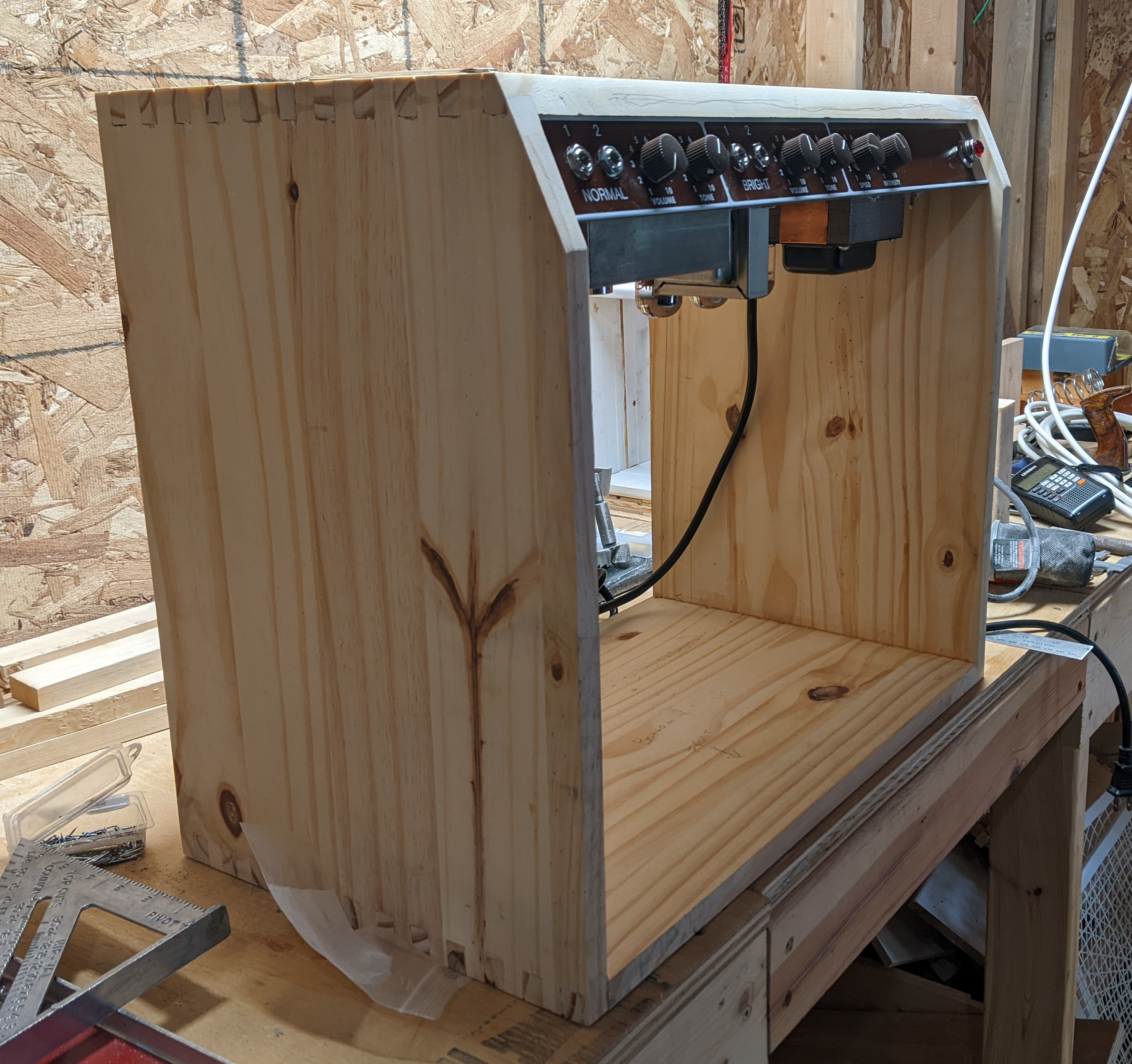
The front of the chassis has a slight angle to it and I wanted to cut a similar angle on the top of the cabinet so I could get to the controls easily. Rather than measure or fiddle with math, I set the circular saw on top of the chassis and adjusted the blade angle until it matched the chassis angle. I took a level and clamped it to the top of the cabinet so that it would position the blade exactly where the cut needed to be. I messed up the cut towards the end and left a ridge but the sander took care of that.

To hold the speaker I used a piece of 3/4 inch birch plywood. I cut it short so that there would be a 1/4 inch gap on all sides to accommodate the grill cloth. I laid the speaker on the center of the plywood and traced it. Then, using a compass and three lines I found the center and traced a smaller circle 1 inch inside the outer circle. This is where the screws to hold the speaker would go. I drilled a hole inside this inner circle and used it to start a jigsaw cut all the way around the inner circle. With that done I laid the speaker over the hole and marked the locations of the screws. I drilled these out and installed T-nuts to give the speaker something sturdy to screw into. A test fit revealed the machine screws were too long so I cut them down with a Dremel. I spray painted the entire speaker baffle black so it wouldn’t show behind the grill cloth. I placed it in the front of the cabinet and set it back about 1/2 inch, then I glued 2 pieces of wood behind it so it could attach to the rest of the cabinet. I wanted to play with my finish nailer so I nailed these support pieces to hold them while the glue dried.

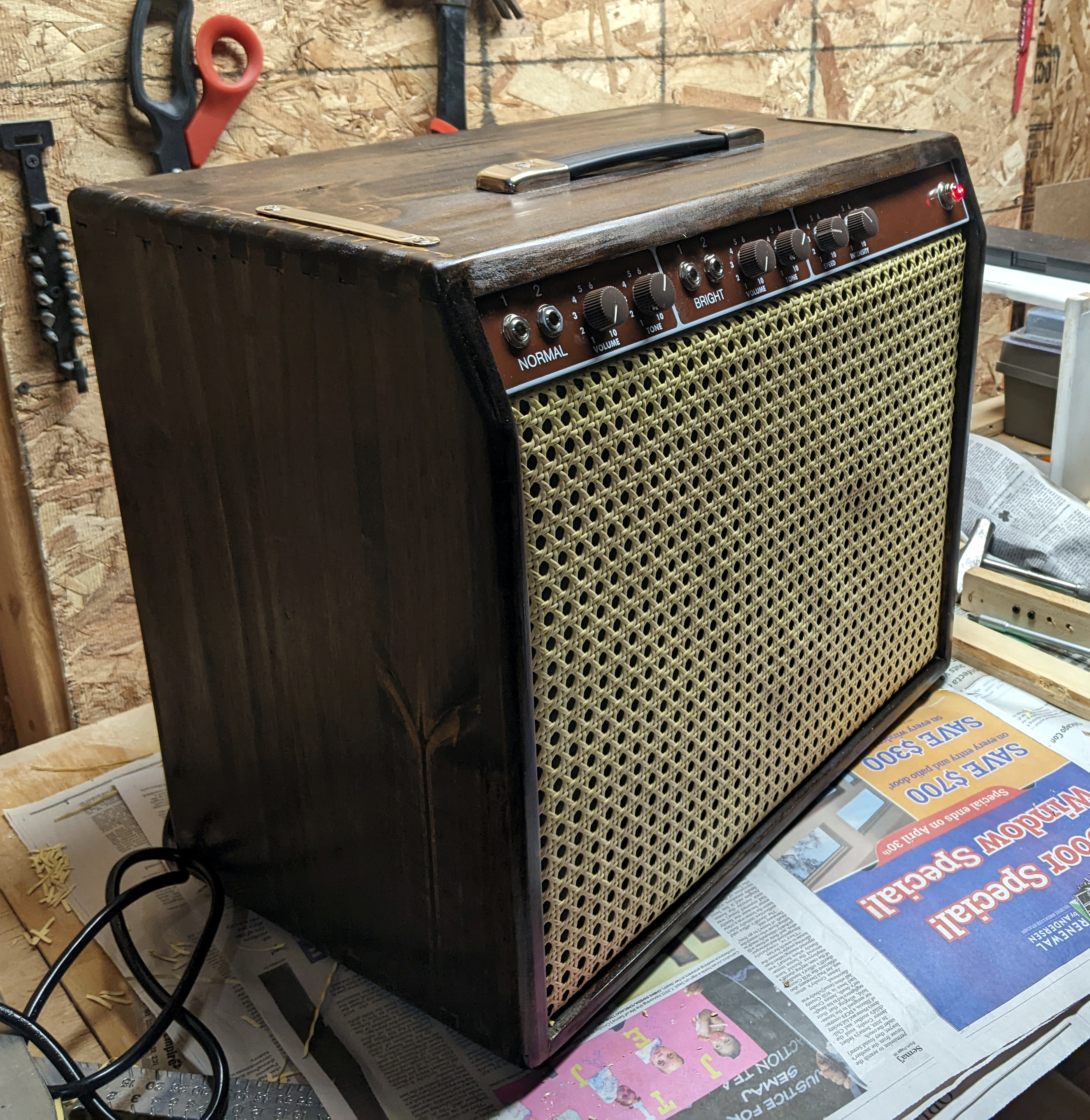
The design I was imitating had a wicker grill. I found a website that sells replacement material for wicker furniture. The roll of material I bought is meant to be used to fix the seat of a chair. I stretched it over the front of the speaker baffle and stapled it behind. Even though I started from the center and worked my way out I still messed this step up and the wicker pattern is not perfectly straight. I am probably the only person who will notice this. (And now you will because I’ve mentioned it.)
I put a roundover bit in the router and practiced on a scrap board to get the depth right. Then I rounded over every outside corner. This was the step when the project started to look good. I sanded the entire cab, working through the grits until the wood no longer felt rough.

Time to paint. I stained the wood with an oak stain and applied three coats of polyurethane - the good kind for outdoor furniture. I haven’t tested it, but I should be able to spill a beer on this amp and it will bounce off. During this step I removed the front baffle and hung the amp to dry between each coat.

I installed the handle - again using T-nuts for a stronger connection - and installed the feet. I slid the chassis in and secured it with the provided top brackets and some long bolts. I screwed the speaker baffle in through the mounting wood I had glued in earlier. I decided not cut the cabinet down to final dimensions because I wasn’t confident I could do it with a circular saw and I didn’t own a table saw. Leaving the cabinet a little deep does not affect the sound. I now own a table saw so I can cut it to final dimensions any time but table saws are really intimidating and I’m not there yet.
6. Finishing up
The final part of this project was building an attenuator. This is a device that bleeds off some of the speaker energy to heat. This amp is only about 15 watts but I have played it at full volume and it rattles the windows and hurts my ears. I’m sure the neighbors could hear it. I don’t want to play at that volume but I want the tubes running hard so I get that sweet tone. The solution is to add some resistance in front of the speaker and convert some of the volume to heat. For larger amps you need to buy an expensive piece of gear called a hot plate that has fans and heatsinks. Because this amp is much smaller I can use something less expensive. I found a rheostat (giant variable resistor) rated for 50 watts for $20. I installed it in an old pedal case and hooked it up between the amp and the speaker. It works really well. Its rating is well above the output power of the amp so I won’t burn it out and it lets me crank the volume on the amp but keep the speaker volume very reasonable.
Overall I’m thrilled with how this project turned out. It was so much fun, except when it was really tedious or scary. I liken it to a set of Legos except with high voltages and solder fumes. The wiring diagrams were so easy to follow. The final product sounds great. I’m still not an expert on amplifier theory, but I have a good idea of what each part of this amp does. And I’m comfortable debugging it. I’m confident that I could troubleshoot the problem if the amp ever stopped working.
7. Mistakes
The biggest mistake I made was not measuring the chassis myself. The documentation said it was 19 inches. I made my cabinet inner width 19 1/4 inches to give myself some wiggle room. However I discovered that the chassis is actually 19 1/4 inches. In a perfect world it would fit exactly. But I do not live in that world. I had to sand the inside of the cabinet many times to give the chassis enough side clearance but finally I got it. I would have liked more clearance but so far the cabinet has been through summer and winter and none of the joints have cracked so it’s probably okay. I was annoyed that I had made such a huge mistake and only discovered it after all of the finger joints were cut.
The other mistake I made was not doing this sooner. My previous amp collected dust for years because it was too loud to play. For whatever reason I held onto it thinking I could bend it to my needs. Sometimes it’s best to admit that something just doesn’t fit, cut it out and move on. Since completing this project last year I have played the new amp almost every day. It has improved my relationship to the guitar and taken my songwriting in new and exciting directions.
8. Future modifications
There are two modifications I plan to make when I’m feeling up to it. The first is changing the bias resistor to a lower value and adding a potentiometer in series so I can fine tune the bias voltage. Using a mutlimeter and some simple math you can determine if the tubes are operating within spec and adjust the bias to bring them in line. This probably isn’t necessary but it will give me more control over how the amp operates. Electronic components in general and vacuum tubes in particular have tolerances and it’s useful to be able to accommodate them.
The second modification is running the negative feedback loop through a switch so that it can be toggled. My naive understanding is that negative feedback is a technique to reduce distortion and give the amp more “headroom” - that is, let you play clean at higher volumes. You take some of the output from the power tubes and feed it back on the input side in such a way that it reduces the grid voltage and limits the signal a little. In this circuit it’s possible to remove the loop entirely and increase the gain a little more. I’d like to have the option for negative feedback, so adding a switch to the loop is a no-brainer.
And of course, I would like to cut the cabinet down so it’s not as deep. But right now I’m happy with the project as-is and in no mood to mess with a good thing.